


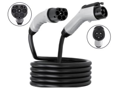


Specify both interfaces and the work between them. Choose the cable format, electrical requirements and handling conditions as one assembly.
Conceptual connection order
Connection A
Cable and usable length
Connection B
Keep complete charging cables, tethered assemblies and extensions separate when comparing a proposal. Their installation and operating requirements differ.
01
For a connection between the charging-equipment outlet and the vehicle inlet. Identify each end, the supply configuration and the vehicle requirements.
02
For equipment integration or a specified replacement. Include the equipment-side termination, controls, dimensions and strain-relief requirements.
03
Define the equipment combination and intended arrangement. Confirm that the applicable equipment instructions permit that use.
A useful comparison includes electrical, mechanical and installation details for the same part number.
Connection at each end; AC or DC; single- or three-phase requirements where relevant.
Required voltage and current, operating pattern and applicable temperature conditions. Do not transfer a rating from a different assembly.
Required usable length, connector orientation, bend and handling requirements, mounting and storage arrangement.
Termination drawing, signal and interlock requirements, sensor functions and replacement procedure where applicable.
For liquid-cooled cable assemblies, include the coolant circuit and monitoring requirements in the specification from the start.
Request the assembly drawing and the operating conditions supporting its proposed current rating. Electrical limits, coolant requirements and the cable length must refer to the same configuration.
Share the equipment, connector at each end, voltage/current requirements, cable length and destination market.